
V1001 General
V1001.1 Scope
The provisions of Chapter 10 shall apply where required by Chapter 2 or where referenced by a requirement in this document.
Advisory V1001.1 Scope Unless otherwise modified or specifically addressed in Chapter 10, all other provisions apply to the design and construction of recreation facilities and elements.The provisions in Section V1001.1 apply wherever these elements are provided.For example, some passenger vessels may contain a room with exercise equipment to which these sections would apply.
V1002 Exercise Machines and Equipment
V1002.1 Clear Deck Space
Exercise machines and equipment shall have a clear deck space complying with V305 positioned for transfer or for use by an individual seated in a wheelchair.Clear deck spaces required at exercise machines and equipment shall be permitted to overlap.
Advisory V1002.1 Clear Deck Space One clear deck space is permitted to be shared between two pieces of exercise equipment.To optimize space use, designers should carefully consider layout options such as connecting ends of the row and center aisle spaces.The position of the clear deck space may vary greatly depending on the use of the equipment or machine.For example, to provide access to a shoulder press machine, clear deck space next to the seat would be appropriate to allow for transfer.Clear deck space for a bench press machine designed for use by an individual seated in a wheelchair, however, will most likely be centered on the operating mechanisms.
V1003 Miniature Golf Facilities
V1003.1 General
Miniature golf facilities shall comply with V1003.
V1003.2 Accessible Routes
Accessible routes serving holes on miniature golf courses shall comply with V402.Accessible routes located on playing surfaces of miniature golf holes shall be permitted to use the exceptions in V1003.2.
EXCEPTIONS
- Playing surfaces shall not be required to comply with V302.2.
- Where accessible routes intersect playing surfaces of holes, a 1 inch (25 mm) maximum curb shall be permitted for a width of 32 inches (815 mm) minimum.
- A slope not steeper than 1:4 for a 4 inch (100 mm) maximum rise shall be permitted.
- Ramp landing slopes specified by V405.7.1 shall be permitted to be 1:20 maximum.
- Ramp landing length specified by V405.7.3 shall be permitted to be 48 inches (1220 mm) long minimum.
- Ramp landing size specified by V405.7.4 shall be permitted to be 48 inches (1220 mm) minimum by 60 inches (1525 mm) minimum.
- Handrails shall not be required on holes.Where handrails are provided on holes, the handrails shall not be required to comply with V503.
V1003.3 Miniature Golf Holes
Miniature golf holes shall comply with V1003.3.
V1003.3.1 Start of Play
A clear deck space 48 inches (1220 mm) minimum by 60 inches (1525 mm) minimum with slopes not steeper than 1:48 shall be provided at the start of play.
V1003.3.2 Golf Club Reach Range Area
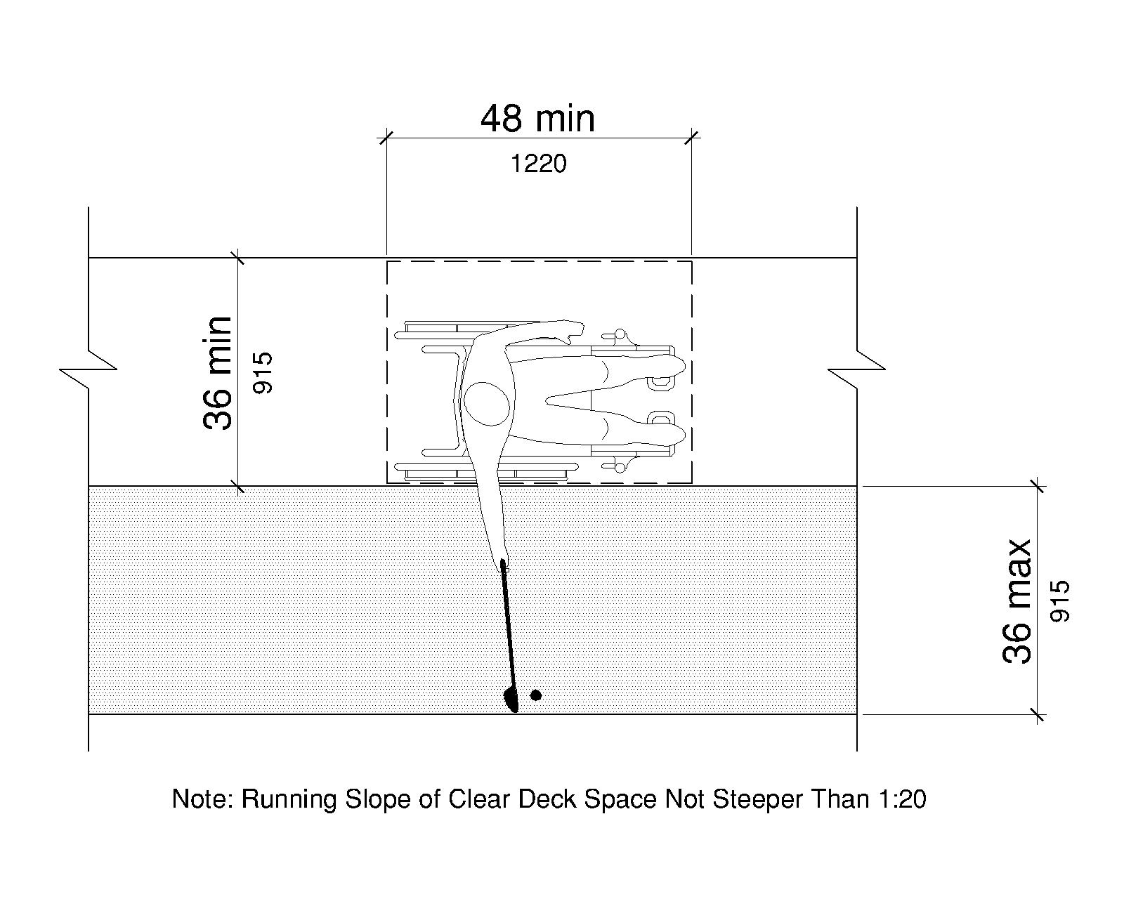
All areas within holes where golf balls rest shall be within 36 inches (915 mm) maximum of a clear deck space 48 inches (1220 mm) long minimum and 36 inches (915 mm) wide minimum having a running slope not steeper than 1:20.The clear deck space shall be served by an accessible route.
Advisory V1003.3.2 Golf Club Reach Range Area The golf club reach range applies to all holes required to be accessible.This includes accessible routes provided adjacent to or, where provided, on the playing surface of the hole.
V1004 Play Areas
V1004.1 General
Play areas shall comply with V1004.
V1004.2 Accessible Routes
Accessible routes serving play areas shall comply with V402 and V1004.2 and shall be permitted to use the exceptions in V1004.2.1 through V1004.2.3.Where accessible routes serve ground level play components, the vertical clearance shall be 80 inches high (2030 mm) minimum.
V1004.2.1 Ground Level and Elevated Play Components
Accessible routes serving ground level play components and elevated play components shall be permitted to use the exceptions in V1004.2.1.
EXCEPTIONS
- Transfer systems complying with V1004.3 shall be permitted to connect elevated play components except where 20 or more elevated play components are provided no more than 25 percent of the elevated play components shall be permitted to be connected by transfer systems.
- Where transfer systems are provided, an elevated play component shall be permitted to connect to another elevated play component as part of an accessible route.
Advisory V1004.2.1 Ground Level and Elevated Play Components The term “ground level” is used in this document and refers to the base level of a playground.Technical assistance material written for landside applications is available at www.access-board.gov and can aid in applying the play area provisions to passenger vessels.
V1004.2.2 Soft Contained Play Structures
Accessible routes serving soft contained play structures shall be permitted to use the exception in V1004.2.2.
EXCEPTION
Transfer systems complying with V1004.3 shall be permitted to be used as part of an accessible route.
V1004.2.3 Water Play Components
Accessible routes serving water play components shall be permitted to use the exceptions in V1004.2.3.
EXCEPTIONS
- Where the surface of the accessible route, clear deck spaces, or turning spaces serving water play components is submerged, compliance with V302, V403.3, V405.2, V405.3, and V1004.2.6 shall not be required.
- Transfer systems complying with V1004.3 shall be permitted to connect elevated play components in water.
V1004.2.4 Clear Width
Accessible routes connecting play components shall provide a clear width complying with V1004.2.4.
V1004.2.4.1 Ground Level
At ground level, the clear width of accessible routes shall be 60 inches (1525 mm) minimum.
EXCEPTIONS
- In play areas less than 1000 square feet (92 m²), the clear width of accessible routes shall be permitted to be 44 inches (1120 mm) minimum provided that at least one turning space complying with V304.3 is provided where the restricted accessible route exceeds 30 feet (9.14 m) in length.
- The clear width of accessible routes shall be permitted to be 36 inches (915 mm) minimum for a distance of 60 inches (1525 mm) maximum provided that multiple reduced width segments are separated by segments that are 60 inches (1525 mm) wide minimum and 60 inches (1525 mm) long minimum.
V1004.2.4.2 Elevated
The clear width of accessible routes connecting elevated play components shall be 36 inches (915 mm) minimum.
EXCEPTIONS
- The clear width of accessible routes connecting elevated play components shall be permitted to be reduced to 32 inches (815 mm) minimum for a distance of 24 inches (610 mm) maximum if reduced width segments are separated by segments that are 48 inches (1220 mm) long minimum and 36 inches (915 mm) wide minimum.
- The clear width of transfer systems connecting elevated play components shall be permitted to be 24 inches (610 mm) minimum.
V1004.2.5 Ramps
Within play areas, ramps connecting ground level play components and ramps connecting elevated play components shall comply with V1004.2.5.
V1004.2.5.1 Ground Level
Ramp runs connecting ground level play components shall have a running slope not steeper than 1:16.
V1004.2.5.2 Elevated
The rise for any ramp run connecting elevated play components shall be 12 inches (305 mm) maximum.
V1004.2.5.3 Handrails
Where required on ramps serving play components, the handrails shall comply with V503, except as modified by V1004.2.5.3.
EXCEPTIONS
- Handrails shall not be required on ramps located within ground level use zones.
- Handrail extensions shall not be required.
V1004.2.5.3.1 Handrail Gripping Surfaces
Handrail gripping surfaces with a circular cross section shall have an outside diameter of 0.95 inches (24 mm) minimum and 1.55 inches (39 mm) maximum.Where the shape of the gripping surface is non-circular, the handrail shall provide an equivalent gripping surface.
V1004.2.5.3.2 Handrail Height
The top of handrail gripping surfaces shall be 20 inches (510 mm) minimum and 28 inches (710 mm) maximum above the ramp surface.
V1004.2.6 Ground Surfaces
Deck surfaces on accessible routes, clear deck spaces, and turning spaces shall comply with V1004.2.6.
V1004.2.6.1 Accessibility
Deck surfaces shall comply with ASTM F1951 (incorporated by reference, see “Referenced Standards” in Chapter 1).Ground surfaces shall be inspected and maintained regularly and frequently to ensure continued compliance with ASTM F1951.
V1004.2.6.2 Use Zones
Deck surfaces located within use zones shall comply with ASTM F1292 (1999 edition or 2004 edition) (incorporated by reference, see “Referenced Standards” in Chapter 1).
V1004.3 Transfer Systems
Where transfer systems are provided to connect to elevated play components, transfer systems shall comply with V1004.3.
V1004.3.1 Transfer Platforms
Transfer platforms shall be provided where transfer is intended from wheelchairs or other mobility aids.Transfer platforms shall comply with V1004.3.1.
V1004.3.1.1 Size
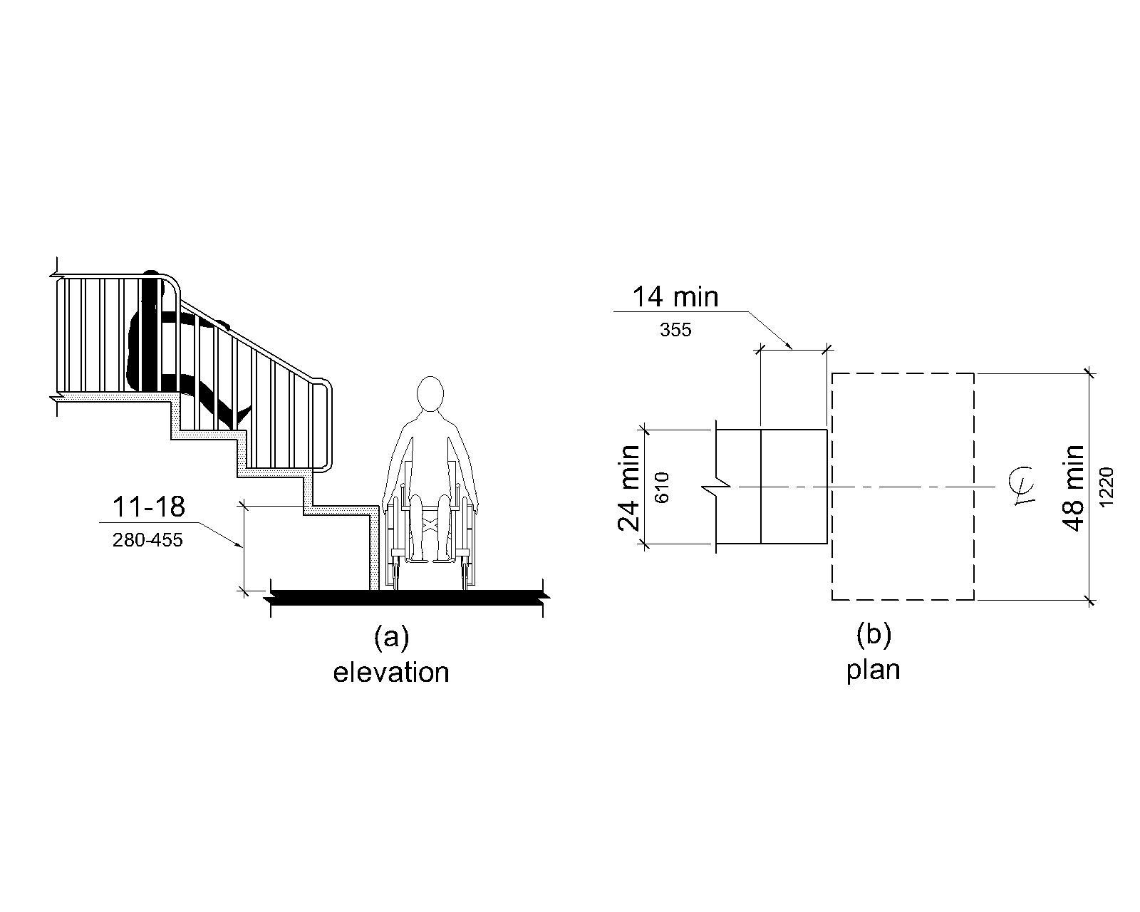
Transfer platforms shall have level surfaces 14 inches (355 mm) deep minimum and 24 inches (610 mm) wide minimum.
V1004.3.1.2 Height
The height of transfer platforms shall be 11 inches (280 mm) minimum and 18 inches (455 mm) maximum measured to the top of the surface from the deck surface.
V1004.3.1.3 Transfer Space
A transfer space complying with V305.2 and V305.3 shall be provided adjacent to the transfer platform.The 48 inch (1220 mm) long minimum dimension of the transfer space shall be centered on and parallel to the 24 inch (610 mm) long minimum side of the transfer platform.The side of the transfer platform serving the transfer space shall be unobstructed.
V1004.3.1.4 Transfer Supports
At least one means of support for transferring shall be provided.
V1004.3.2 Transfer Steps
Transfer steps shall be provided where movement is intended from transfer platforms to levels with elevated play components required to be on accessible routes.Transfer steps shall comply with V1004.3.2.
V1004.3.2.1 Size
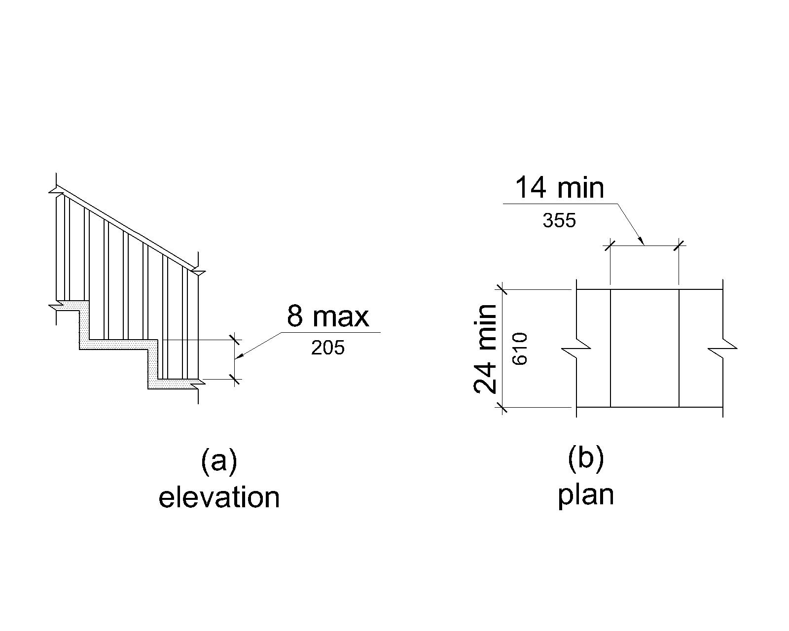
Transfer steps shall have level surfaces 14 inches (355 mm) deep minimum and 24 inches (610 mm) wide minimum.
V1004.3.2.2 Height
Each transfer step shall be 8 inches (205 mm) high maximum.
V1004.3.2.3 Transfer Supports
At least one means of support for transferring shall be provided.
V1004.4 Play Components
Ground level play components on accessible routes and elevated play components connected by ramps shall comply with V1004.4.
V1004.4.1 Turning Space
At least one turning space complying with V304 shall be provided on the same level as play components.Where swings are provided, the turning space shall be located immediately adjacent to the swing.
V1004.4.2 Clear Deck Space
Clear deck space complying with V305.2 and V305.3 shall be provided at play components.
V1004.4.3 Play Tables
Where play tables are provided, knee clearance 24 inches (610 mm) high minimum, 17 inches deep (430 mm) minimum, and 30 inches (760 mm) wide minimum shall be provided.The tops of rims, curbs, or other obstructions shall be 31 inches (785 mm) high maximum.
EXCEPTION
Play tables designed and constructed primarily for children 5 years and younger shall not be required to provide knee clearance where the clear deck space required by V1004.4.2 is arranged for a parallel approach.
V1004.4.4 Entry Points and Seats
Where play components require transfer to entry points or seats, the entry points or seats shall be 11 inches (280 mm) minimum and 24 inches (610 mm) maximum from the clear deck space.
EXCEPTION
Entry points of slides shall not be required to comply with V1004.4.4.
V1004.4.5 Transfer Supports
Where play components require transfer to entry points or seats, at least one means of support for transferring shall be provided.
V1005 Swimming Pools, Wading Pools, and Spas
V1005.1 General
Where provided, pool lifts, sloped entries, transfer walls, transfer systems, and pool stairs shall comply with V1005.
V1005.2 Pool Lifts
Pool lifts shall comply with V1005.2.
Advisory V1005.2 Pool Lifts There are a variety of seats available on pool lifts ranging from sling seats to those that are preformed or molded.Pool lift seats with backs will enable a larger population of persons with disabilities to use the lift.Pool lift seats that consist of materials that resist corrosion and provide a firm base to transfer will be usable by a wider range of people with disabilities.Additional options such as armrests, head rests, seat belts, and leg support will enhance accessibility and better accommodate people with a wide range of disabilities.
V1005.2.1 Seat Location
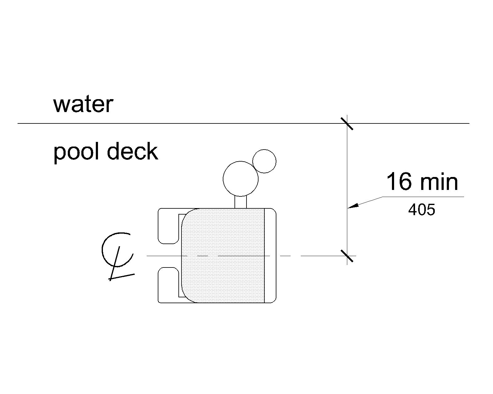
In the raised position, the centerline of the seat shall be located over the deck surface and 16 inches (405 mm) minimum from the edge of the pool.The deck surface between the centerline of the seat and the pool edge shall have a slope not steeper than 1:48.
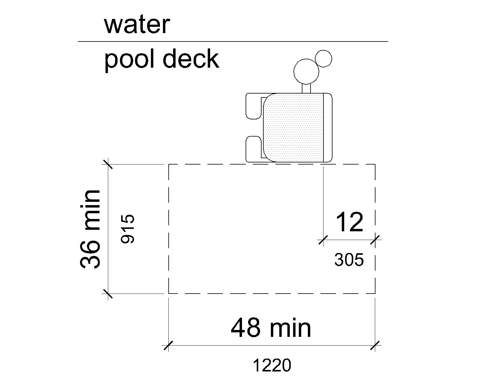
V1005.2.2 Clear Deck Space
On the side of the seat opposite the water, a clear deck space shall be provided parallel with the seat.The space shall be 36 inches (915 mm) wide minimum and shall extend forward 48 inches (1220 mm) minimum from a line located 12 inches (305 mm) behind the rear edge of the seat.The clear deck space shall have a slope not steeper than 1:48.
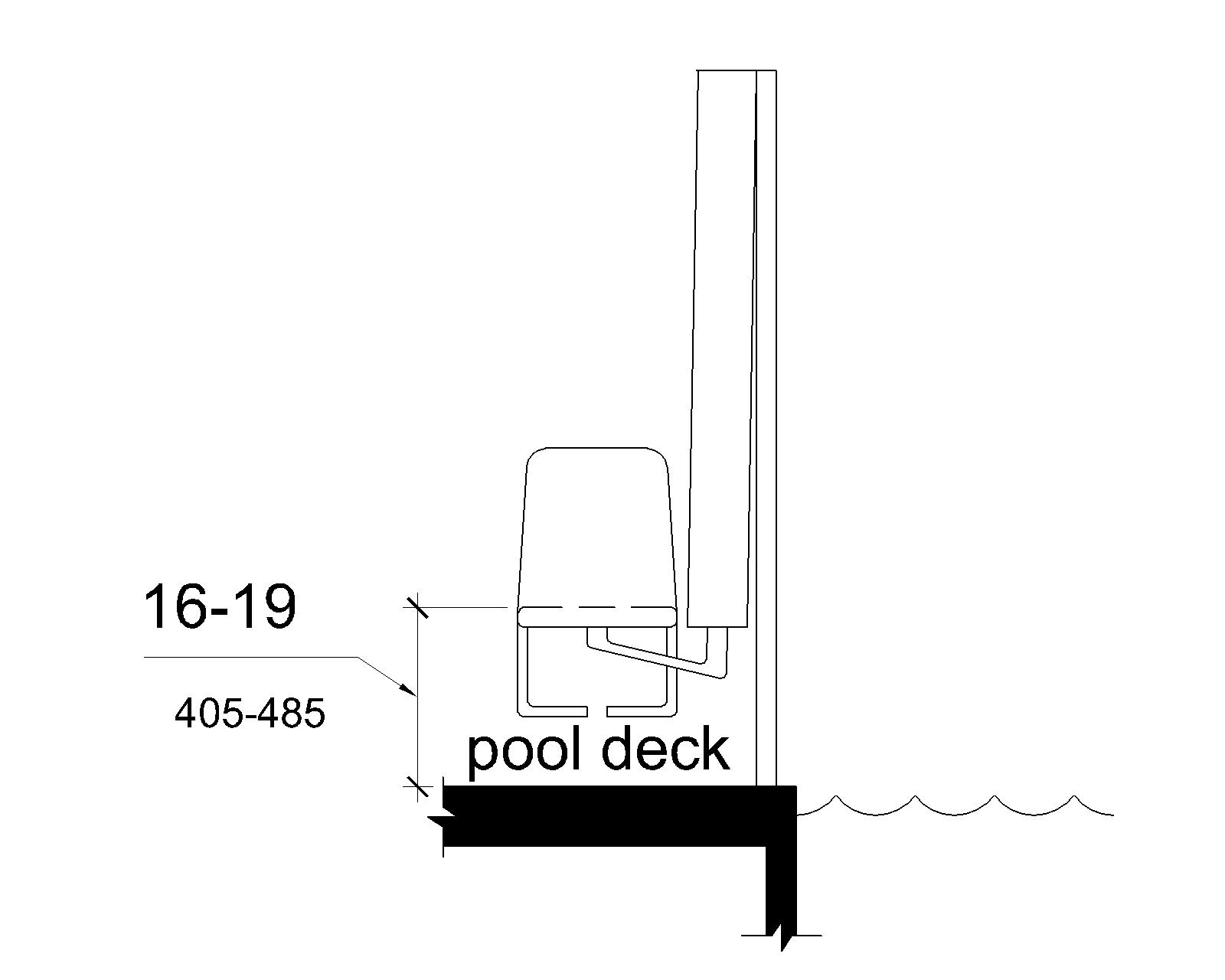
V1005.2.3 Seat Height
The height of the lift seat shall be designed to allow a stop at 16 inches (405 mm) minimum to 19 inches (485 mm) maximum measured from the deck surface to the top of the seat surface when in the raised (load) position.
V1005.2.4 Seat Width
The seat shall be 16 inches (405 mm) wide minimum.
V1005.2.5 Footrests and Armrests
Footrests shall be provided and shall move with the seat.If provided, the armrest positioned opposite the water shall be removable or shall fold clear of the seat when the seat is in the raised (load) position.
EXCEPTION
Footrests shall not be required on pool lifts provided in spas.
V1005.2.6 Operation
The lift shall be capable of unassisted operation from both the deck surface and water levels.Controls and operating mechanisms shall be unobstructed when the lift is in use and shall comply with V309.4.
Advisory V1005.2.6 Operation Pool lifts must be capable of unassisted operation from both the deck and water levels.This will permit a person to call the pool lift when the pool lift is in the opposite position.It is extremely important for a person who is swimming alone to be able to call the pool lift when it is in the up position so he or she will not be stranded in the water for extended periods of time awaiting assistance.The requirement for a pool lift to be independently operable does not preclude assistance from being provided.
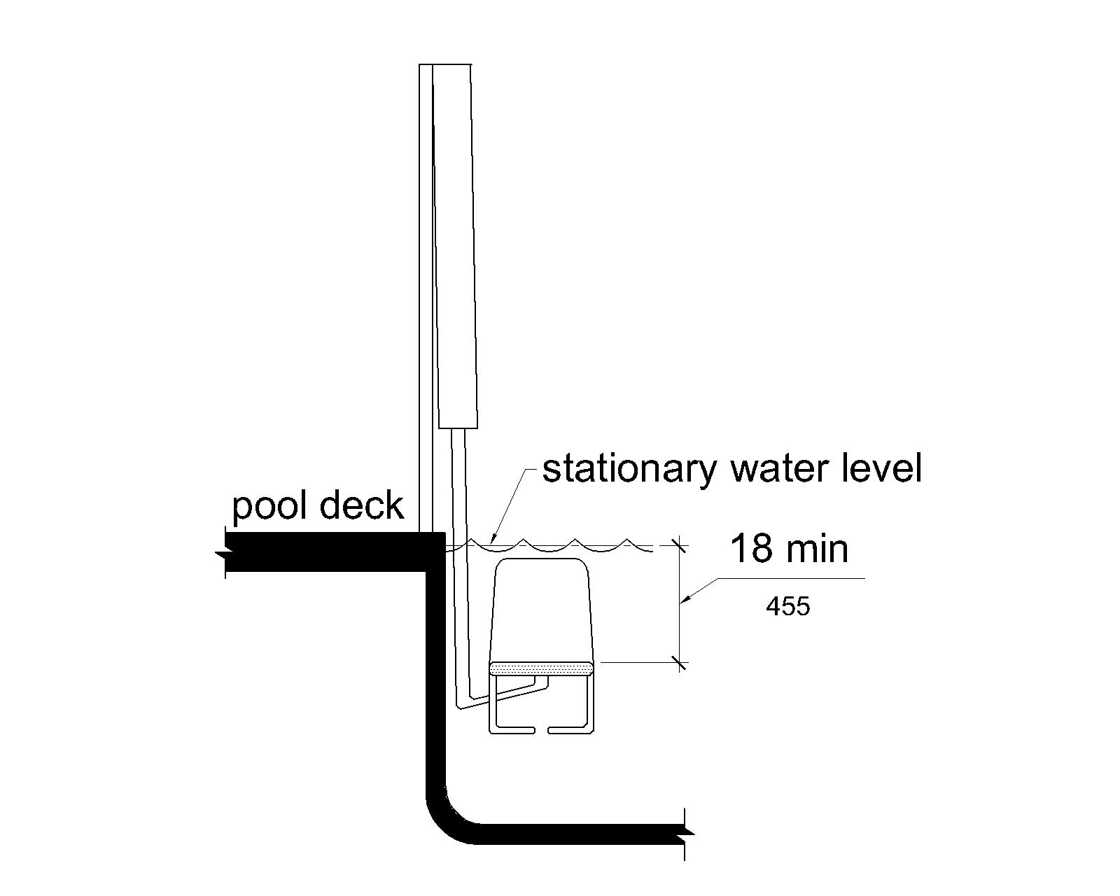
V1005.2.7 Submerged Depth
The lift shall be designed so that the seat will submerge to a water depth of 18 inches (455 mm) minimum below the stationary water level.
Advisory V1005.2.7 Submerged Depth As pool lifts are required by V1005.2.5 to be equipped with footrests, water depths greater than 18 inches (455 mm) are needed to properly submerge the seat of pool lifts.To allow the opportunity for someone to provide assistance from a standing position in the water to lift users, it is recommended that a portion of the pools where pool lifts are located have water depths that do not exceed 48 inches (1220 mm).
V1005.2.8 Lifting Capacity
Single person pool lifts shall have a weight capacity of 300 pounds (136 kg) minimum and be capable of sustaining a static load of at least one and a half times the rated load.
Advisory V1005.2.8 Lifting Capacity Single person pool lifts must be capable of supporting a minimum weight of 300 pounds (136 kg) and sustaining a static load of at least one and a half times the rated load.Providing a pool lift with a weight capacity greater than 300 pounds (136 kg) may be advisable.
V1005.3 Sloped Entries
Sloped entries shall comply with V1005.3.
Advisory V1005.3 Sloped Entries Personal wheelchairs and mobility devices may not be appropriate for submerging in water.Some may have batteries, motors, and electrical systems that when submerged in water may cause damage to the personal mobility device or wheelchair or may contaminate the pool water.Providing an aquatic wheelchair made of non-corrosive materials and designed for access into the water will protect the water from contamination and avoid damage to personal wheelchairs or other mobility aids.
V1005.3.1 Sloped Entries
Sloped entries shall comply with V402 except as modified in V1005.3.1 through V1005.3.3.
EXCEPTION
Where sloped entries are provided, the surfaces shall not be required to be slip resistant.
V1005.3.2 Submerged Depth
Sloped entries shall extend to a depth of 24 inches (610 mm) minimum and 30 inches (760 mm) maximum below the stationary water level.Where landings are required by V405.7, at least one landing shall be located 24 inches (610 mm) minimum and 30 inches (760 mm) maximum below the stationary water level.
EXCEPTION
In wading pools, the sloped entry and landings, if provided, shall extend to the deepest part of the wading pool.
V1005.3.3 Handrails
At least two handrails complying with V503 shall be provided on the sloped entry.The clear width between required handrails shall be 33 inches (840 mm) minimum and 38 inches (965 mm) maximum.
EXCEPTIONS
- Handrail extensions specified by V503.10.1 shall not be required at the bottom landing serving a sloped entry.
- Where a sloped entry is provided for wave action pools, leisure rivers, sand bottom pools, and other pools where user access is limited to one area, the handrails shall not be required to comply with the clear width requirements of V1005.3.3.
- Sloped entries in wading pools shall not be required to provide handrails complying with V1005.3.3.If provided, handrails on sloped entries in wading pools shall not be required to comply with V503.
V1005.4 Transfer Walls
Transfer walls shall comply with V1005.4.
V1005.4.1 Clear Deck Space
A clear deck space of 60 inches (1525 mm) minimum by 60 inches (1525 mm) minimum with a slope not steeper than 1:48 shall be provided at the base of the transfer wall.Where one grab bar is provided, the clear deck space shall be centered on the grab bar.Where two grab bars are provided, the clear deck space shall be centered on the clearance between the grab bars.
V1005.4.2 Height
The height of the transfer wall shall be 16 inches (405 mm) minimum and 19 inches (485 mm) maximum measured from the deck surface.
V1005.4.3 Wall Depth and Length
The depth of the transfer wall shall be 12 inches (305 mm) minimum and 16 inches (405 mm) maximum.The length of the transfer wall shall be 60 inches (1525 mm) minimum and shall be centered on the clear deck space.
V1005.4.4 Surface
Surfaces of transfer walls shall not be sharp and shall have rounded edges.
V1005.4.5 Grab Bars
At least one grab bar complying with V609 shall be provided on the transfer wall.Grab bars shall be perpendicular to the pool wall and shall extend the full depth of the transfer wall.The top of the gripping surface shall be 4 inches (100 mm) minimum and 6 inches (150 mm) maximum above transfer walls.Where one grab bar is provided, clearance shall be 24 inches (610 mm) minimum on both sides of the grab bar.Where two grab bars are provided, clearance between grab bars shall be 24 inches (610 mm) minimum.
EXCEPTION
Grab bars on transfer walls shall not be required to comply with V609.4.
V1005.5 Transfer Systems
Transfer systems shall comply with V1005.5.
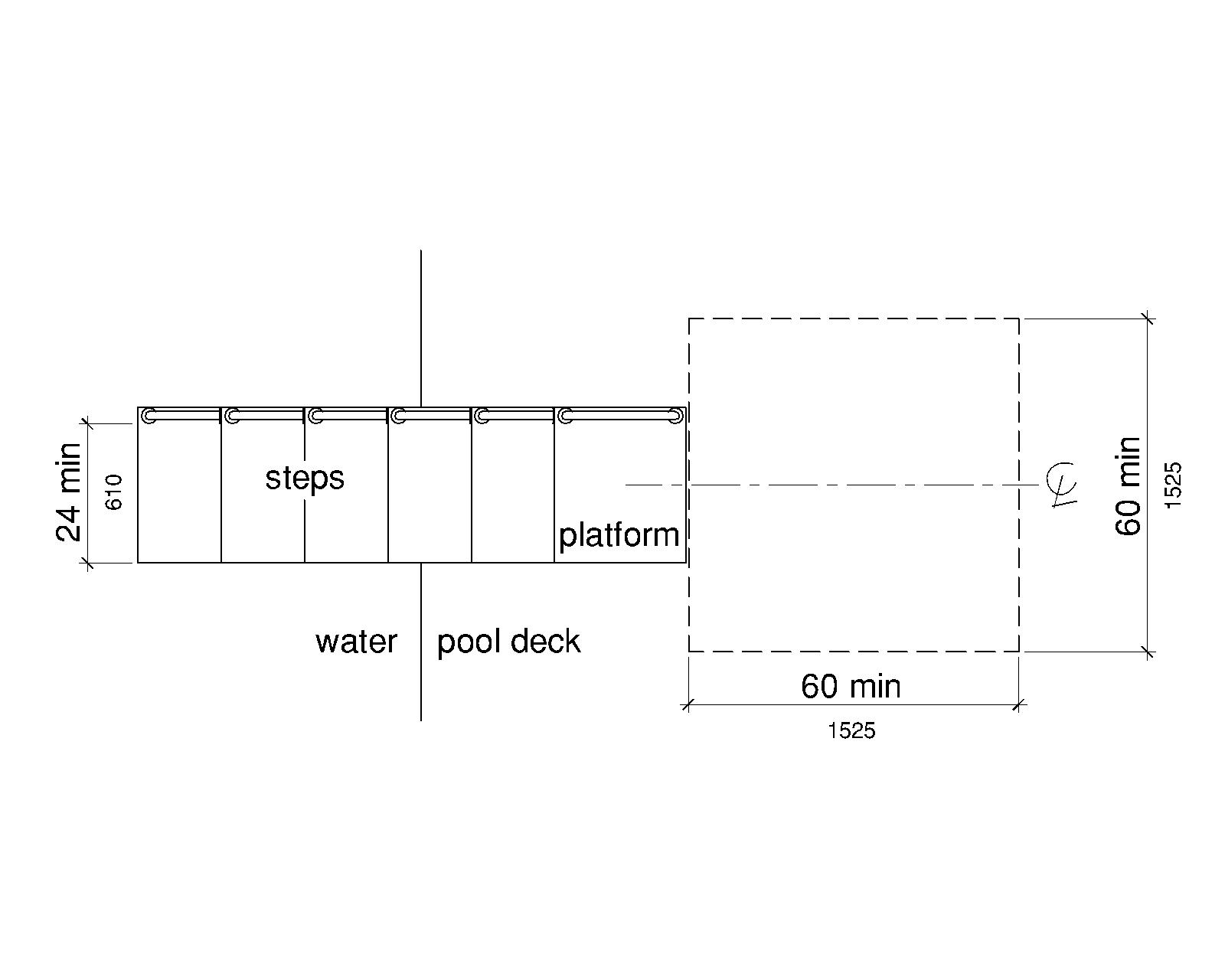
V1005.5.1 Transfer Platform
A transfer platform shall be provided at the head of each transfer system.Transfer platforms shall provide 19 inches (485 mm) minimum clear depth and 24 inches (610 mm) minimum clear width.
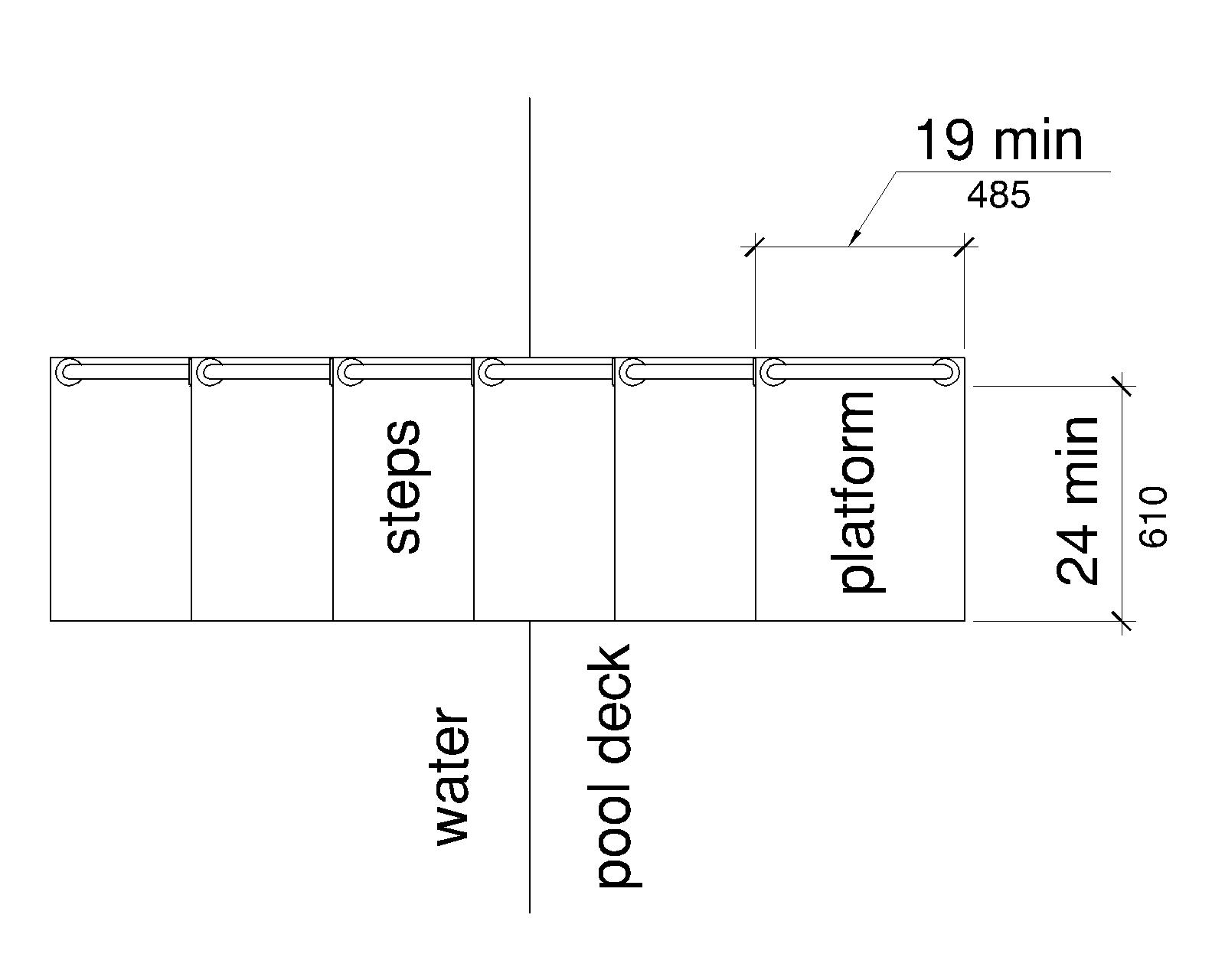
V1005.5.2 Transfer Space
A transfer space of 60 inches (1525 mm) minimum by 60 inches (1525 mm) minimum with a slope not steeper than 1:48 shall be provided at the base of the transfer platform surface and shall be centered along a 24 inch (610 mm) minimum side of the transfer platform.The side of the transfer platform serving the transfer space shall be unobstructed.
V1005.5.3 Height
The height of the transfer platform shall comply with V1005.4.2.
EXCEPTION
Transfer platforms which serve wading pools are permitted to have a height of 11 inches (280 mm) minimum and 18 inches (455 mm) maximum measured to the top of the platform surface from the deck surface.
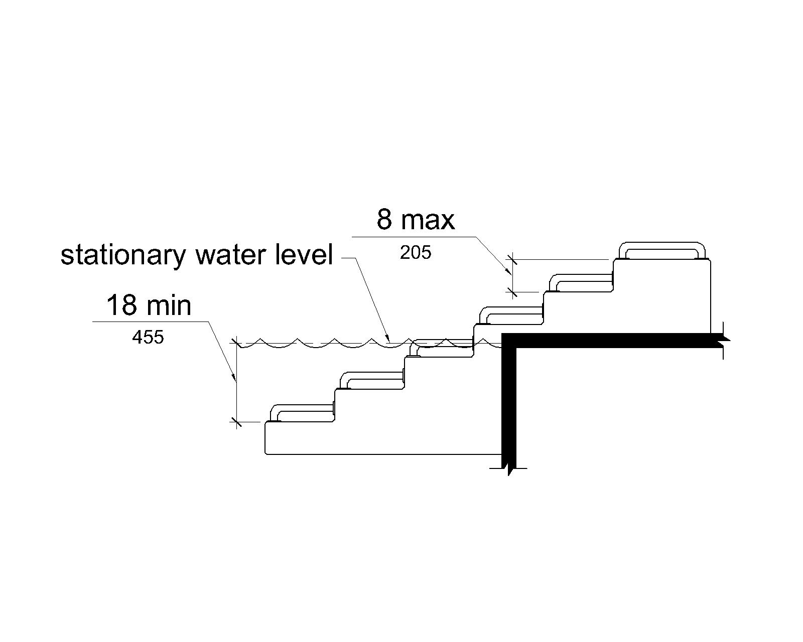
V1005.5.4 Transfer Steps
Transfer step height shall be 8 inches (205 mm) maximum.The surface of the bottom tread shall extend to a water depth of 18 inches (455 mm) minimum below the stationary water level.
EXCEPTION
In wading pools where the depth of the water is less than 18 inches (455 mm), the water depth of the bottom tread surface is permitted to be equal to the depth of the pool.
Advisory V1005.5.4 Transfer Steps Where possible, the height of the transfer step should be minimized to decrease the distance an individual is required to lift up or move down to reach the next step to gain access.
V1005.5.5 Surface
The surface of the transfer system shall not be sharp and shall have rounded edges.
Advisory V1005.5.5 Surface People using the transfer system may have skin contact with the surfaces of the transfer system.Care should be taken in selecting surface materials.Some materials require more maintenance and may be subject to splintering which might cause skin injuries and related health complications.Padding of transfer surfaces may further protect people during use of such systems.
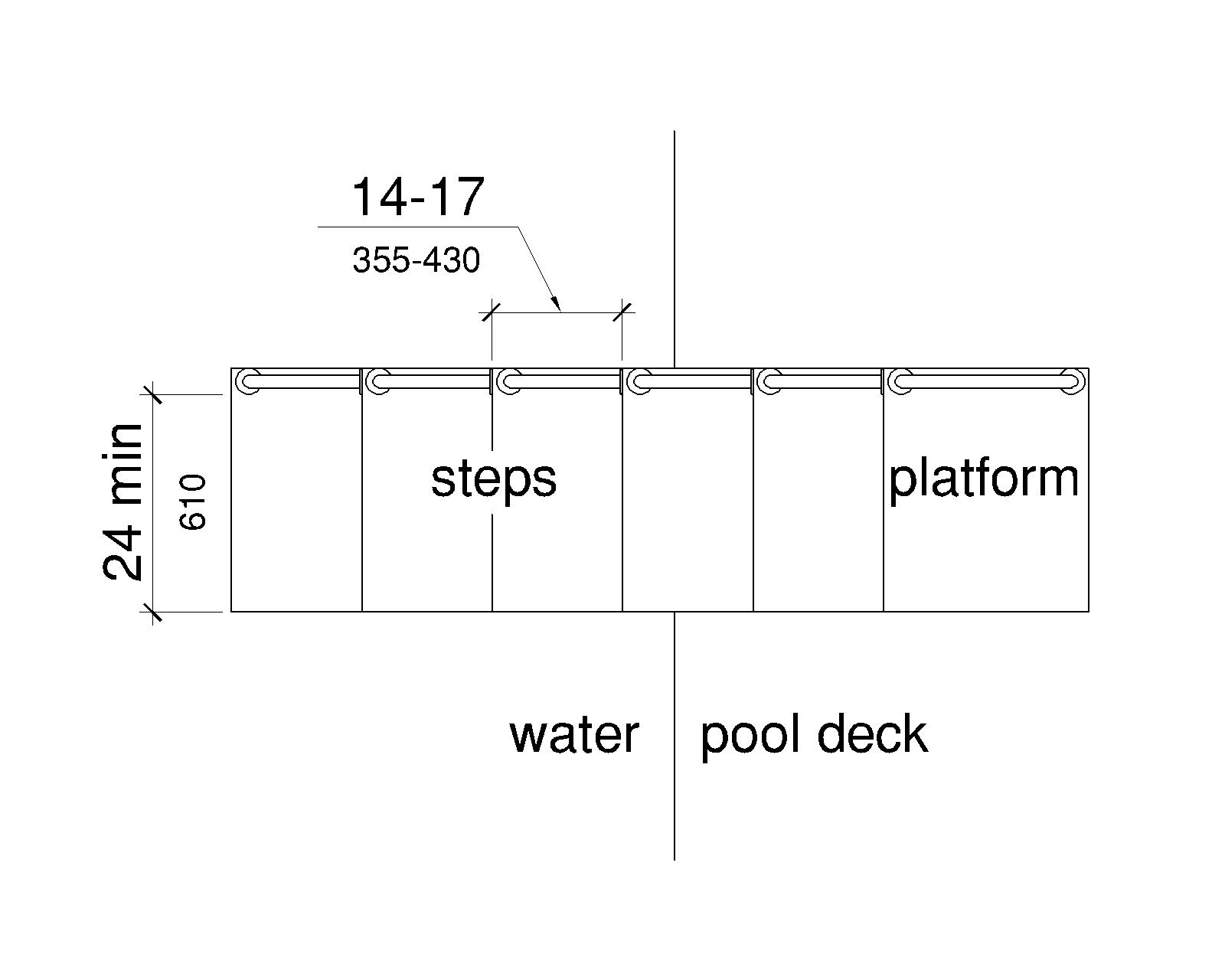
V1005.5.6 Size
Each transfer step shall have a tread clear depth of 14 inches (355 mm) minimum and 17 inches (430 mm) maximum and shall have a tread clear width of 24 inches (610 mm) minimum.
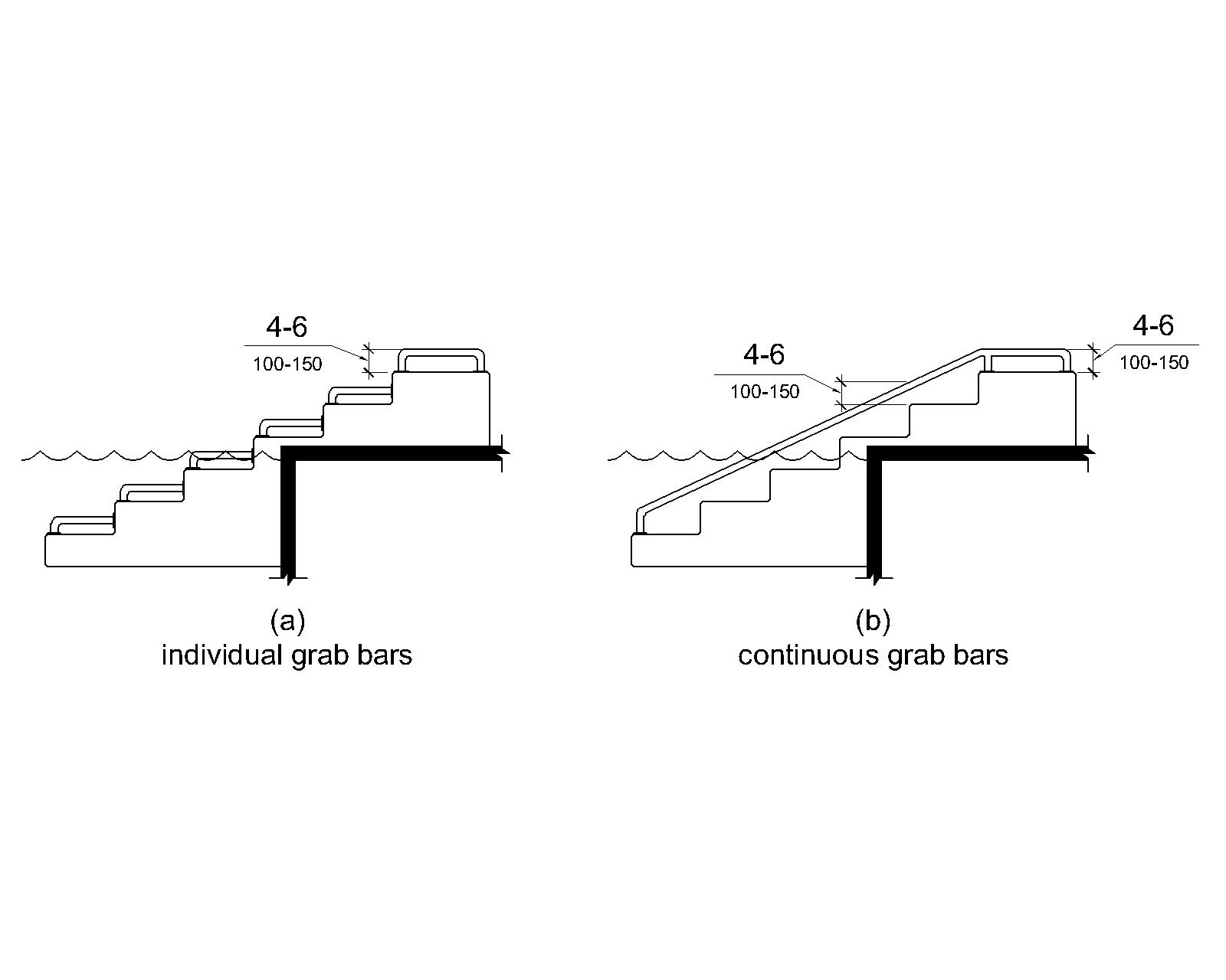
V1005.5.7 Grab Bars
At least one grab bar on each transfer step and the transfer platform or a continuous grab bar serving each transfer step and the transfer platform shall be provided.Where a grab bar is provided on each step, the tops of gripping surfaces shall be 4 inches (100 mm) minimum and 6 inches (150 mm) maximum above each step and transfer platform.Where a continuous grab bar is provided, the top of the gripping surface shall be 4 inches (100 mm) minimum and 6 inches (150 mm) maximum above the step nosing and transfer platform.Grab bars shall comply with V609 and be located on at least one side of the transfer system.The grab bar located at the transfer platform shall not obstruct transfer.
EXCEPTION
Grab bars on transfer systems shall not be required to comply with V609.4.
V1005.6 Pool Stairs
Pool stairs shall comply with V1005.6.
V1005.6.1 Pool Stairs
Pool stairs shall comply with V502.
V1005.6.2 Handrails
The width between handrails shall be 20 inches (510 mm) minimum and 24 inches (610 mm) maximum.
V1006 Shooting Positions
V1006.1 Turning Space
A circular turning space 60 inches (1525 mm) diameter minimum with slopes not steeper than 1:48 shall be provided at shooting positions.
