
Trail Study Sites
An Access Board solicitation for potential playground study sites yielded numerous responses for trail work as well. An accessibility coordinator for the Wisconsin State Parks of-fered us an opportunity not far from the Forest Products Laboratory, at Governor Dodge State Park in Dodgeville, Wisconsin—to extend an accessible beach path and to attempt to stabilize two short sections of a severely eroded bridle path.
Beach Path
Our prototype test location for the SEWF concept on trails was an accessible beach path to Cox Hollow Lake. The existing path was 1.2-m- (4-ft-) wide blacktop asphalt extending 50 m (165 ft) from accessible parking to the be-ginning of the sand beach, 30 m (100 ft) from the water. Our task was to provide accessibility over the sand to the water, retaining the aesthetic quality of the area (National Center on Accessibility 2003).
Discussions with the park staff provided insight to the usage of the beach path. The desire was for park users to be able to maneuver a wheelchair directly to the water’s edge, where they could access the beach and a boat landing (Fig. 1). Another consideration was the proximity of the path to the beach volleyball area. The SEWF surfaces were originally developed for use as impact-sensitive playground surfaces. Thus, their impact behavior was considered much more forgiving than that of an asphalt path.
Layout of the path across the beach was sloped so that the edge of the path would not hold water. Park personnel were concerned that sand would wash or get kicked over the path surface, which would decrease accessibility and increase maintenance requirements. Slope along the upper edge was a minimum of 1%. Nearer the waterline the slope of the path increased to a maximum of approximately 5% for the final few meters (feet). The amount of waterline fluctuation was considered minimal at this beach because of the proximity of water control structures.
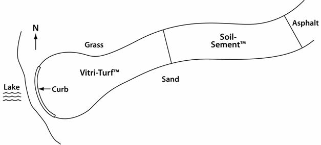
Figure 1—Schematic plan of Governor Dodge State Park Cox Hollow beach path site (not to scale).
We first lowered and leveled the existing sand surface to a depth of 0.06 m (2.4 in.) (Fig. 2). Any stones and vegetation near the waterline were removed. Within 1.5 m (5 ft) (hori-zontal distance) of the waterline, the stability of the sand was deemed inadequate for supporting the SEWF. We removed 0.1 m (4 in.) of sand in this area and replaced it with 20 mm (3/4 in.) of angular stone to provide a well-drained and stable base, which would also reduce the amount of scour from wave action on the lake. The work crew consisted of employees of the park, the Wisconsin Department of Natural Resources, and the USDA Forest Service.
A lightweight landscaping geotextile fabric was placed on the sand and drainage rock. Handfuls of sand were thrown on the fabric to keep the wind from blowing it out of place. The geotextile fabric bonded to the SEWF and improved overall stability of the surface layer.
Bridle Path
Both bridle path sections were remote sites that required the use of hand tools for surface preparation. The surfaces were prepared by removing large rocks and woody forest debris.
One site consisted of two parallel ruts approximately 0.1 to 0.2 m (4 to 8 in.) deep and 0.2 to 0.3 m (8 to 12 in.) wide. The ruts were within 1 m (3 ft) apart on a 15% to 20% slope. Native soil was exposed along the ruts. The soil was firm with little loose soil or unstable rock.
The other site was a 3-m (12-ft) wide section on a bridle trail with a 20% to 25% slope leading to a level wash that carried water during heavy rains for very short periods.
The primary objective was to stabilize the soil from the erosive forces of horse hooves and water running across the wash.
Bonded Beach Path Installation
The two binder systems used to fabricate the beach path surface were
1. an acrylic and polyvinyl acetate polymer emulsion, Soil-Sement (Midwest Industrial, Canton, Ohio), mixed 30% by dry weight of solids to unit weight of dry EWF and applied 63 mm (2-1/2 in.) thick, and
2. a non-foaming polyurethane, Vitri-Turf (Vitricon, Polymer Plastics Corp., Commack, New York), mixed 30% by weight with unit dry weight of EWF and applied 37 mm (1-1/2 in.) thick.
Because the installation occurred in the fall, we monitored air temperature; both stabilizing binders required 4°C (40°F) for proper curing. On the date of installation, the overnight temperature was 7°C (44°F). The binders had been stored at room temperature. When the binders were mixed with EWF, the temperature of the mixture was well above 10°C (50°F). The EWF was shoveled directly from the truck into a 160-L (40 gal) portable mortar mixer. The amount of binder added was determined as a proportion (30%) of EWF dry weight (volumetrically equivalent to 0.041 m3 (1.45.ft3) of EWF to 5.3 L (1.25 gal) of Vitri-Turf or 10.6 L (2.5 gal) of Soil-Sement. Weight proportion was 77:23. The binder and EWF were mixed for approximately 2 min and transported to the target pad in polyethylene tray wheelbarrows (Fig. 3). The binder–EWF mixture was spread with hand tools to an even thickness (Figs. 4 and 5). The area was then compacted and flattened with a 1.2-m by 1.2-m by 16-mm (4-ft by 4-ft by 5/8-in.) piece of plywood covered with a polyethylene re-lease sheet. A 90-kg (198-lb) person walked on the plywood in each quadrant to apply firm compaction pressure. At the termination of the path at the waterline a 0.1-m (3.5-in.) curb was formed to reduce any inadvertent rolling of the path into the water and to stiffen the edge directly in contact with wave action.
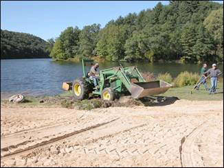
Figure 2—Grading of beach path to waterline.
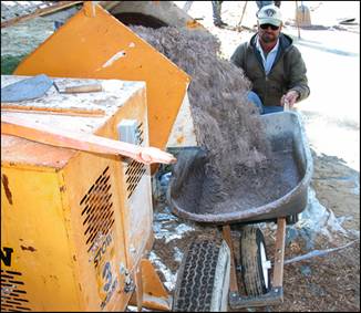
Figure 3—Loading of binder–EWF mixture from mortar mixer into wheelbarrow.
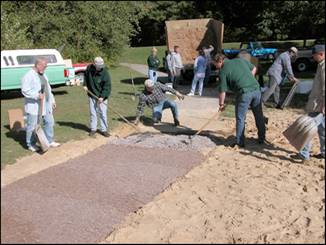
Figure 4—Leveling and compaction of binder– EWF mixture near junction with asphalt path.
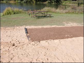
Figure 5—Termination of Soil-Sement portion of beach path. Geotextile fabric visible under completed SEWF surface.
The two SEWF surfaces were allowed to cure or bond for 5 days prior to use (Fig. 6). Because rain was not predicted, the entire surface was left exposed. Overnight temperatures stayed above 4°C (40°F) for 2 days after installation. Within 2 h of installing the Vitri-Turf, the surface was somewhat rigid to hand pressure. The Soil-Sement surface was slower to stiffen and was deemed stiff within 48 h. Five days after installation, the barriers were removed and the edge of the path was backfilled with beach sand using rakes. The com-pleted beach path after 2 months of weathering is shown in Figure 7.
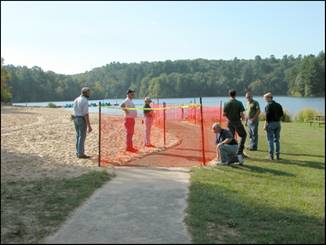
Figure 6—Completed beach path area looking west, shown with temporary barrier for 5-day SEWF curing period.
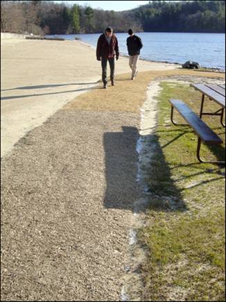
Figure 7—Beach path after 2 months of weathering. Junction of Soil-Sement and Vitri-Turf surfaces is just above the shadow cast by the picnic bench.
Bonded Bridle Path Installation
The same two binder systems used to fabricate the beach path surface (Soil-Sement and Vitri-Turf) were used for the bridle path trials.
Prior to the date of installation, the overnight temperature was 9°C (48°F). The binders had been stored at room temperature; when mixed with EWF, the resultant mixture was well above 10°C (50°F).
For both systems, the layer of EWF placed on the soil surface was 0.05 to 0.07 m (2 to 3 in.) deep and was raked smooth. A backpack sprayer and drip-bucket were used to apply the Soil-Sement (approximately 50% solids content) with a target application proportion of 30% binder based on the weight/volume of EWF (Figs. 8 and 9). The Vitri-Turf was much more viscous (100% solids) and thus only a drip bucket approach was used to apply the binder (Fig. 10).
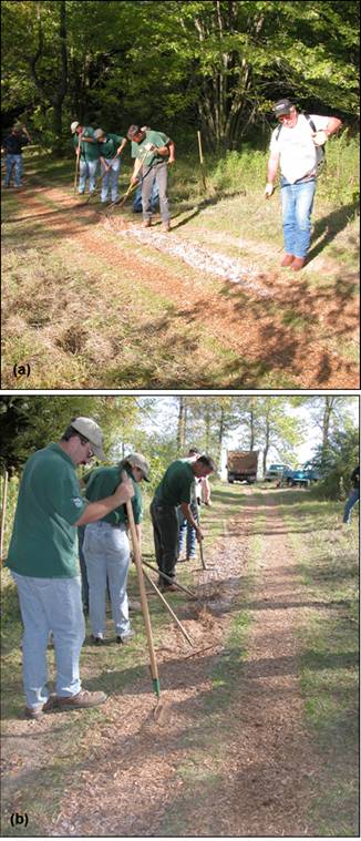
Figure 8—Installation of Soil-Sement surface on bridle path: (a) application of Soil-Sement by backpack-type sprayer; (b) trail crew mixed, leveled, and compacted the narrow trail filled with SEWF.
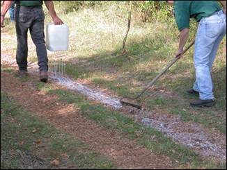
Figure 9—Application of Soil-Sement to bridle trail by drip-bucket method. Rakes were used to mix binder with EWF and level the trail.
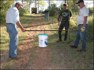
Figure 10—Application of Vitri-Turf to bridle trail by drip-bucket method. Holes drilled in bottom of 19-L (5-gal) container allowed uniform application over 0.4- by 20-m
(1.3- by 66-ft) trail.
With a known weight of EWF at an application proportion of 30%, 19 L (5 gal) of binder was applied by moving a perfo-rated bucket (holes 6 mm (0.2 in.) in diameter) quickly over the surface. Immediately after applying the binder, the binder was mixed into the EWF with forks and garden rakes. On the narrow bridle path, the SEWF was compacted using the flat end of a rake. The wider path was compacted using a poly-ethylene-covered 1.2-m by 1.2-m by 16-mm (4-ft by 4-ft by 5/8-in.) piece of plywood; a 90-kg (198-lb) person walked on the plywood in each quadrant to apply firm compaction pressure (Fig. 11). The SEWF areas were roped off for 5 days to provide time for curing prior to usage.
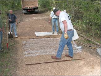
Figure 11—Treatment of wide bridle trail (site 2): spray application of Vitri-Turf in ackground and drip-bucket application of Soil-Sement in foreground. Note use of polyethylene-covered plywood for compaction and leveling of Vitri-Turf SEWF.
Test Procedures
Field Observation Reports
The sites were not under direct supervision or observation by park staff or other responsible personnel. However, on-duty staff noted any public concerns and changes at the site and reported them when we visited. Forest Products Laboratory staff visited the sites at least weekly for the first 2 months and at least monthly thereafter (if the ground was thawed) to complete the rotational penetrometer testing and to observe and annotate any maintenance needs.
Impact Attenuation Tests
Impact tests were completed on the beach path only as an adjunct to tests conducted at a playground at another park. For the beach path, we were interested if the impact standard could be met when SEWF was placed over sand. The impact was conducted by a cooperator (Zeager Bros. Inc., Middle-town, Pennsylvania) 8 weeks after installation. ASTM F 1292–99 test specifications (ASTM 1999a) and F355–95 test methods (ASTM 1995) were used at a test drop height of 3.05 m (10.0 ft) and 1.83 m (6.0 ft), respectively. Maximum g levels and head injury criteria (HIC) were measured.
Accessibility and Durability Measures
The beach path surfaces were periodically measured with a rotational penetrometer. This device subjects the test surface to a low-speed rotational bearing test meant to simulate the weight and action of a front caster wheel on a wheelchair. The procedures are based on the draft national standard test method for the firmness and stability of ground and floor surfaces (RESNA 2000), which uses an average of five readings. This test provides objective measures of surface firmness and stability. Although no literature has been pub-lished on this subject, the use of the rotational penetrometer data allows an inference to the durability of the binder–EWF surface. The test effectively detects the loss of bond strength during the stability (rotation of caster wheel) portion of the test. The firmness measure is a means of inferring changes in overall stiffness of the bonded layer as well. It has been correlated to the work measurement of ASTM F1951 (ASTM 1999b), “Accessibility of Surface Systems,” for a wide array of surfacing and floor coverings. The test was performed 1 week after surface installation and as often as once a week initially, using a Beneficial Designs, Inc. (Minden, Nevada) rotational penetrometer and protocol for assessing the bearing/rotational indentation on each surface (Axelson and Chesney 1999).